In today’s rapidly advancing technological landscape, printed circuit boards (PCBs) are crucial in powering various electronic devices. Whether it’s your smartphone, computer, or even the car you drive, PCBs are the backbone that enables these devices to function efficiently. This comprehensive guide will explore the world of PCBs, discussing their definition, types, composition, design considerations, and applications.
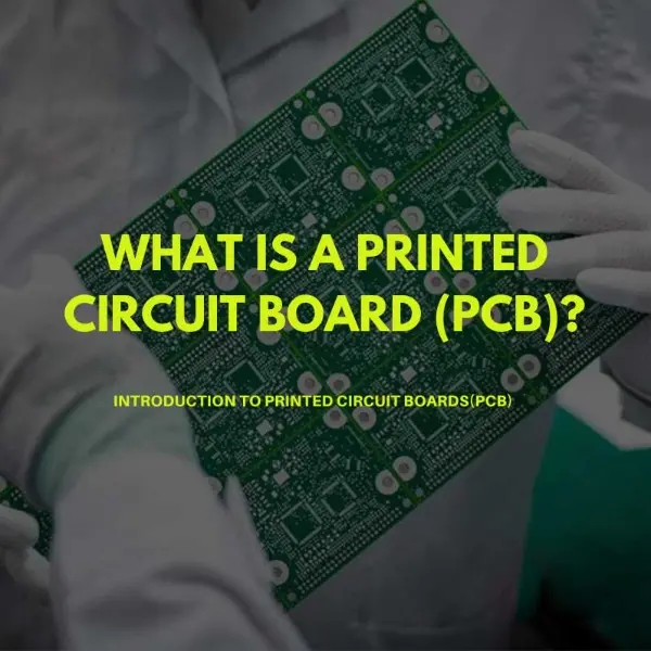
Part 1: What is a PCB? (Printed Circuit Board)
A printed circuit board, commonly known as a PCB, is a flat board made of non-conductive material, typically fiberglass, with conductive pathways etched or printed onto its surface. These pathways, known as traces or copper tracks, carry electrical signals between various components on the board. PCBs provide a sturdy platform that supports and connects electronic components, allowing them to function as a cohesive unit.
Part 2: Printed circuit board types
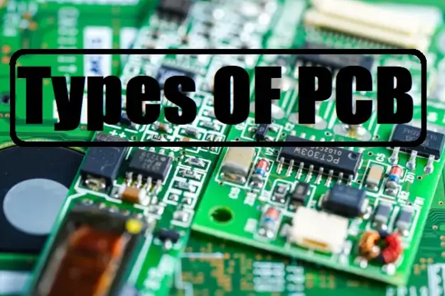
PCBs come in different types, each catering to specific requirements and applications. Let’s explore some of the common types of PCBs:
1. Single-Sided PCBs
Single-sided PCBs feature conductive traces on only one side of the board. These are simple and cost-effective, making them suitable for basic applications with minimal circuit complexity.
2. Double-sided PCBs
Double-sided PCBs have conductive traces on both sides of the board, connected through vias (plated holes). They offer increased circuit density and are widely used in consumer electronics, automotive systems, and industrial equipment.
3. Multilayer PCBs
Multilayer PCBs consist of multiple layers of conductive traces separated by insulating material. These boards provide greater design flexibility, higher circuit density, and improved signal integrity. They are commonly found in complex electronic devices such as smartphones, computers, and advanced control systems.
4. Rigid PCBs
Rigid PCBs are made from inflexible materials such as fiberglass or composite epoxy. They are sturdy and suitable for applications where the board needs to maintain a fixed shape, such as in desktop computers or industrial machinery.
5. Flexible PCBs
Flexible PCBs, also known as flex PCBs, are made from flexible materials like polyimide. They can bend or twist without losing functionality, making them ideal for applications with space constraints or complex form factors. Flexible PCBs are commonly used in medical devices, wearable technology, and automotive systems.
6. Rigid-Flex PCBs
Rigid-flex PCBs combine the advantages of both rigid and flexible PCBs. These boards consist of rigid and flexible sections interconnected, providing a versatile solution for applications that require a combination of structural integrity and flexibility.
Part 3. Printed circuit board components
1. Resistors
Resistors are passive components that regulate electrical current within a circuit. They limit the flow of current, control voltage levels, and provide stability to the overall system.
2. Capacitors
Capacitors store and release electrical energy. They help stabilize voltage levels, filter out noise, and provide temporary power during voltage fluctuations.
3. Integrated Circuits (ICs)
Integrated circuits, or ICs, are miniaturized electronic circuits that contain multiple interconnected components, such as transistors, resistors, and capacitors. They perform specific functions and are the building blocks of complex electronic systems.
4. Diodes
Diodes allow electrical current to flow in only one direction and prevent reverse flow. They are crucial for converting alternating current (AC) to direct current (DC), among other applications.
5. Transistors
Transistors amplify or switch electronic signals. They are fundamental components in amplifiers, digital logic circuits, and other electronic systems.
6. Connectors
Connectors facilitate the physical connection between the PCB and external devices. They allow the transfer of power, data, and signals.
Part 4. Printed circuit board design
Design Considerations
In designing a printed circuit board (PCB), several critical factors need consideration to ensure optimal performance:
- Component Placement: Strategically positioning components on the PCB to minimize signal interference and optimize space utilization.
- Routing: Efficiently routing traces to connect components while maintaining signal integrity and minimizing electromagnetic interference.
- Signal Integrity: Ensuring signals propagate through the PCB without distortion or loss, often achieved through impedance matching and careful trace routing.
- Thermal Management: Managing heat dissipation to prevent component overheating and maintain reliability, which involves considerations like copper pour and heatsink placement.
To achieve these goals, engineers utilize various design software tools and techniques:
- Design Software Tools: Use CAD (Computer-Aided Design) software such as Altium Designer or Eagle to create schematics and layouts.
- Optimization Techniques: Implementing design optimization techniques like Design Rule Checking (DRC) and Design for Manufacturability (DFM) to ensure design efficiency and manufacturability.
Manufacturing Process
The manufacturing process of PCBs involves several sequential steps:
- Substrate Preparation: The base material, often fiberglass-reinforced epoxy, is prepared by cutting it into panels of appropriate sizes.
- Imaging: Applying a light-sensitive material called photoresist to the substrate, then exposing it to UV light through a mask to transfer the PCB pattern.
- Etching: Using chemical solutions to selectively remove copper from areas not protected by the photoresist, leaving behind the desired circuit traces.
- Drilling: Creating holes for component leads and vias using precision drilling machines to facilitate electrical connections.
- Plating: Depositing a thin layer of metal (usually copper) onto the walls of the drilled holes to enhance conductivity and facilitate soldering.
- Solder Mask Application: Applying a protective layer of solder mask over the PCB surface, leaving only the desired areas exposed for soldering.
Quality control measures are integral throughout the manufacturing process:
- Inspection: Regular inspection of materials and processes to identify defects or deviations from specifications.
- Testing Procedures: Conducting electrical tests, such as continuity and insulation resistance tests, to ensure the integrity of the finished PCBs.
Part 5. Printed circuit board applications
1. Consumer Electronics
PCBs are at the heart of numerous consumer electronic devices, including smartphones, laptops, televisions, and gaming consoles. They enable the seamless integration of various components and ensure the reliable performance of these devices.
2. Automotive Industry
Modern vehicles heavily rely on PCBs for their electrical and electronic systems. PCBs are used in engine management, infotainment, driver assistance, and more. They enhance vehicle performance, safety, and connectivity.
3. Industrial Equipment
Industrial machinery and equipment often utilize PCBs to control and monitor processes. From manufacturing automation to robotics, PCBs enable precise control, data acquisition, and communication in industrial settings.
4. Medical Devices
PCBs are crucial in the medical field, powering intricate medical devices and equipment. They are found in devices such as MRI machines, pacemakers, patient monitoring systems, and diagnostic equipment, ensuring accurate and reliable medical procedures.
5. Aerospace and Defense
In aerospace and defense, PCBs are used in avionics systems, communication equipment, radar systems, and satellite technology. They provide the necessary reliability and performance in demanding environments.
Part 6. FAQs
-
What is the difference between a PLC and a printed circuit board?
The difference between a PLC and a printed circuit board is that a PLC (Programmable Logic Controller) is an electronic device used for industrial automation and control. In contrast, a printed circuit board (PCB) is a physical board that provides support and connectivity for electronic components. -
Do PCBs use AC or DC?
Depending on the application and the components connected to the board, PCBs can be used with AC (alternating current) and DC (direct current). -
Why do printed circuit boards fail?
Printed circuit boards can fail for various reasons, such as manufacturing defects, improper handling or installation, environmental factors like heat or moisture, component failures, or electrical overloads. -
What is the function of printed circuit boards for lithium-ion batteries?
PCBs in lithium-ion batteries manage charging, balance cell voltages, provide protection, and enable communication with external devices.
Related Tags:

More Articles

Overview of Deep Cycle Lithium Battery
In this article, we explore the life, voltage, capacity, and charging considerations of deep cycle lithium batteries.
How Long do Lithium Batteries Last?
How long do lithium batteries last? we will explore the factors that influence the lifespan of lithium batteries and provide insights into their longevity.
How to Choose the Best LiFePO4 Battery?
Choose LiFePO4 batteries for superior performance, safety, and versatility in EVs, UPS, and backup power. This guide helps you make informed decisions.
Get 12v Lithium Car Battery As a Power Source for the Ride
Make the right choice for your vehicle's battery needs by installing a 12 volt lithium car battery. You will enjoy maintenance-free longevity with this change.